Building Computing Machines from Ground Up: Nuts and Bolts
revision 0.8.2
In this post I will discuss the options available to a reasonably dedicated hobbyist building a computer from ground up, their strong and weak points. I will constrain myself to devices that need electricity to operate.
Maze of twisty little components
The moment I decided to work on a computer I got to decide which technology it will be based on. In the XXI century one can design and implement very complex systems using FPGAs, but I wanted to use discrete components to achieve this goal. The most obvious choice – logic chips – just creates more questions. Which level of integration should be considered discrete? Should the design be implemented with basic logic gates only or is medium-level of integration fine? Or maybe to abandon all fears and to go with transistors? And more importantly what is the plan to deal with memory? As Mr. Müeller has once put it, it looks strange when you implement your CPU using discrete transistors and then throw in a few millions of them in a form of RAM chip. Actually RAM design choice could provide a lot of headache, since to be able to compute something interesting one will need substantial amounts of memory, and by substantial I mean hundreds of bytes which is not that much considering modern standards, but could mean either hours of toil or substantial spendings. For instance when each byte is made separately from discrete transistors – it takes about one hundred of them per byte. And letting you mind run wild it is easy to come up with even more general question: whether it is feasible to build a practical computer from raw elements like silicon, copper, maybe some zinc oxide? It doesn’t sound all that crazy given that people state that they can build nonlinear elements and even memristors out of rather mundane elements, so maybe it is worth it to try to repeat such success and get super awesome memristor memory? (I considered all these options and homemade transistors look like a realistic goal, however extremely labor intensive. As for memristors those turned to be a disappointment since I have repeatedly failed to reproduce reported results let alone to build something out of them).
Over time I have considered and eventually rejected multiple options most feasible of which are presented in the handy table below:
Basic elements          Clock Freq, Hz        Effort       Power Consumption
----------------------------------------------------------------------------
Relays                         5            Medium-High     Medium-High
Magnetic circuits             1k            High            Medium
Vacuum tubes                 10k            High            Very High
Gas-filled tubes              1k            High            Low-Medium
Transistors                  50k            Medium-High     Low
Other chips                  50k            Medium          Low
Logic gates                  50k            Medium          Low
MSI chips                   100k            Low-Medium      Very Low
Here basic element is the minimal unit available to the designer, clock frequency is a ballpark estimate for maximum clock speed which could be achieved without serious tuning, effort is the expected amount of effort (roughly speaking time and money product) required to put into a computer, power consumption is yet another ballpark estimate of amount of power needed for the thing to run with “Low” being below 100W and “High” above 1kW.
Let’s discuss each option in greater details. Relays go first in the table so let us start with them. Relays are simple electro-mechanical devices which could be switched on or off by passing a current through them. Being able to switch between two states immediately makes them a good match for binary logic building blocks.

a. Relay AND gate; b. Relay NOT gate.
Of course relays have been used multiple times in many interesting designs which should not discourage anybody willing to try a hand at designing another relay computer or two.
What I like about relays is that they could be built out of very basic low-tech materials. All you really need to start rolling your own relays are a spool of magnet wire and some scrap iron. Basic hand tools could be helpful as well, but a really determined person could probably build them by just applying brute force and sheer willpower.

DIY relay. "In" is input terminal, "O1" and "O2" are output terminals; "In" is normally collected to "O2". When current is passing through control coil "CC" (between control terminals "+C" and "-C") magnetic material "IP" moves down and pulls on "MC" connector which disconnects "In" from "O2" and connects it to "O1".
Of course you could buy factory made relays, but that could either limit what could be done or skyrocket the price. Consider for example a register. To build one out of stock element one would need to either seek latching relays or to go ahead and implement triggers out of common off-the-shelve relays which would requires at least two of them per bit. However when rolling your own relays one could consider building the following contraption:

Latch "L" is suspended on a spring and could be moved by passing current through terminals "+L" and "-L" of latch coil "LC". When current is passing through "LC" "L" allows for free movement of relay armature "IP" fixing it in one of two positions after current through "LC" has stopped.
Here the switch is kept in position by the latch which gets moved when current flows through LC terminals. To write new value one must first unlatch armature of data relay and apply new value. After switch changes its positions the latch goes down and fixes it in place where it stays no matter what happens to current through data terminals. What makes this design different from factory-made latching relays is the ability to add arbitrary number of storing elements so if one needs sixty four bit relay register this could be easily the most cost-efficient way to get it. Also note, that a register built of triggers drains current all the time while mechanical latches consume power only when switching to new state.
Following this line of thought one could easily come up with multiple interesting components: bus switches, oscillators and what not. But before you have started planning your very special relay computer be warned, relays have downsides. First of all they are rather big, you should not expect sizes less then a couple of cubic centimeters for commercially available specimen or rather labor-intensive home-made ones. They consume power, typical values of switching current are about 5mA at 5V. 25mW does not sound like a lot until you remember that you’ll easily end up with several of those per bit of storage and much more for actual processing. So while not exorbitant power budget could be rather high. The relays are not designed for and can’t switch too fast – technically you can get hundreds of Hertz in oscillating circuits, but for a practical digital circuit it is safer not to expect frequencies higher than several Hertz. Also relays tend to develop issues after some number of switchings especially when it was switching high current: arcing erodes the surfaces of contacts and make them unreliable. On the plus side you get vintage look and lots and lots of clicking noises when running a relay computer. Ultimately unwillingness to invest into buying massive amounts of factory-made relays and the amount of work required to build enough customized relays made me rule this option out.
The next option is rather esoteric by modern standards – magnetic circuits.

a. Magnetic OR gate; b. Magnetic NOT gate; c. Magnetic shift register. Here thick circles represent ferrite rings with loops standing for windings. Note that magnetic logic works with either alternating current or with pulses.
A core made of ferromagnetic material with several coils can amplify or switch alternating currents, so could be used as a building block for larger logic elements. On the plus side they are rather rugged – it takes power to actually burn copper wire and as there are no moving parts or parts operating at extreme conditions chances of failure of individual components are low, individual elements are relatively cheap and easy to manufacture, replace and repair, they can operate at relatively high frequency and consume relatively small amount of power. The downsides are the size, and most importantly the amount of work needed to build all elements needed – in some manual on magnetic circuits I have seen an estimate of five minutes per core to build a single gate. Since there are virtually no such devices readily available on the market in case I chose them it would have required me to design and build a small industrial line for assembling and testing magnetic elements which was way above my expected time budget so unfortunately it was ruled out as well.
Vacuum tubes being amplifiers could be easily tricked into behaving like switches with resulting schematics resembling transistor-based logic elements.
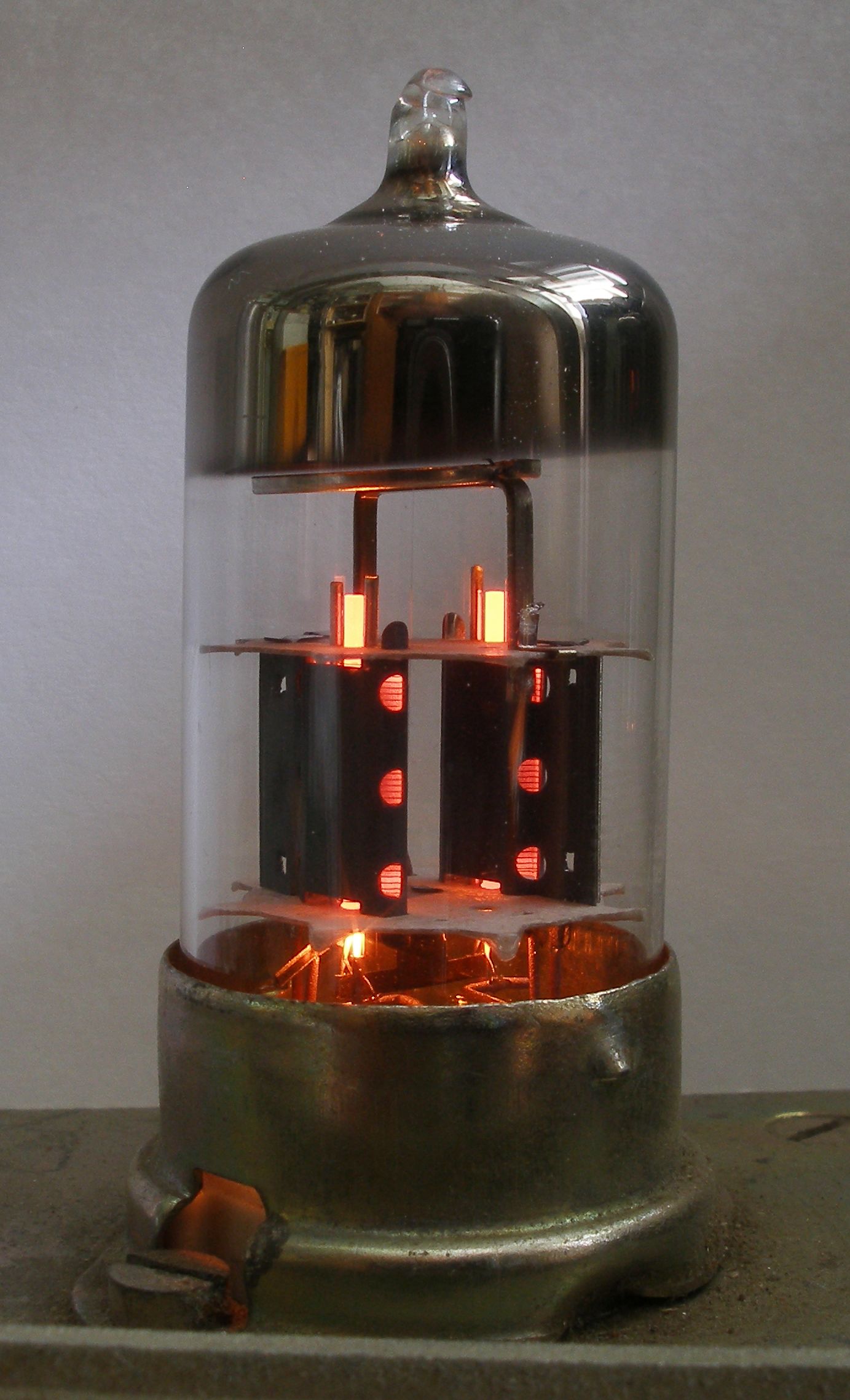
Double triode in action. Photo by ScAvenger licensed under CC-BY-AL

Triode based NOR gate.
Vacuum tubes are rather fast easily allowing for clock frequencies of hundreds of kilohertz and could be either found in surplus stores or relatively easily built from scratch (note, however, that relatively easy in this case means a small workshop equipped with a vacuum system and enough spare time). On the downside vacuum tubes have relatively short lifespan (from thousands to tens of thousands hours), are rather prone to failures (so operating an installation of hundreds to thousands of vacuum tubes could easily be reduced to non-stop search for failed elements) and consume lots and lots of power – each tube requiring at least a full Watt of power. So while exceptionally aesthetically pleasing vacuum tubes were ruled out almost immediately.
The next option is quite exotic as well – gas-filled tubes which in the days of yonder were an element of choice for building inexpensive counting devices. It was so lucrative to use gas discharge for the purpose of counting that special counting devices – decatrons – have been designed and successfully used in early computers. While decatrons have become an obscure rarity in the modern day used mostly for building decorative vintage-looking clocks, it is worth remembering, that counting circuits have been built out of ordinary neon lamps and three terminal thyratrons, sometimes called relay tubes, allow for easier control over when a lamp starts conducting.
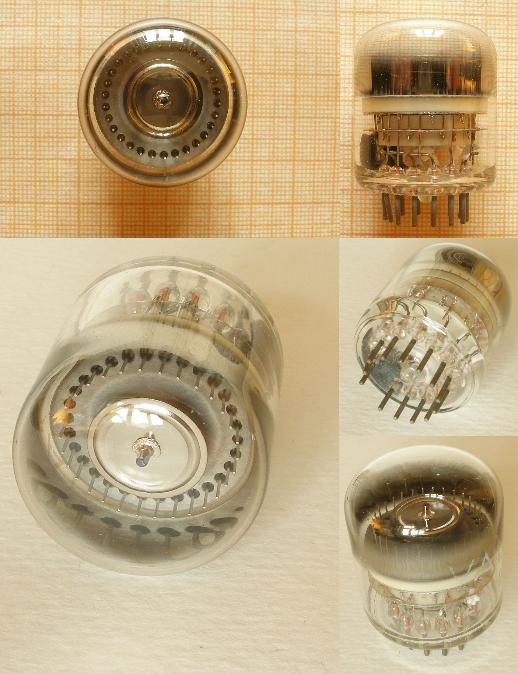
Decatron, a counting tube. Photo by ScAvenger licensed under CC-BY-AL

Ring counter counts up to four pulses before rolling over. Each new pulse lights up the next neon bulb in the queue simultaneously extinguishing the previous one.
Being much smaller, much less power-hungry than hard-vacuum devices and allowing for somewhat simpler technology stack for those willing to build them from scratch gas-filled tubes come with significant downside – it is easy to make an element conduct, it is much harder to cut the current and requires separate circuitry. In terms of logic gates it means that while AND and OR gates are trivial, NOT can’t be easily built which leaves us with incomplete set of logic functions. This effectively negates all potential gain from their usage in general purpose logic gates and reduces gas-filled devices to counters. Unfortunately it does not seem to be feasible to build a computer purely from gas-filled elements and even if it were possible it would have required significant effort, not less than needed for building a computer from discrete transistor. Thus I ruled out gas-filled devices.
The next three options – transistors, other chips and small-scale integration circuits all bear very similar traits. They all are very close to be practically useful (in case of transistors especially if one buys them instead of building them from scratch). Transistor based computers have been build multiple times. Also transistor gates are extremely well documented so I won’t even include picture of one – they are literally everywhere. No real challenges here once you figure out how to build NAND gate except for the need to set up a process of circuit board manufacturing – that has actually made me abandon this route as well, or to at least postpone it to some distant future. The same holds true for the remaining options of the group – other chips and discrete logic gates. While discrete logic gates are quite obvious elements and I won’t spend much time discussing them, I would like to pay some attention to other chips.
When considering integrated options other than special purpose logic gates first thing that comes to mind is operational amplifiers. While most useful for analog computers they can easily be made to perform logic operations. Below is an image of gates made out of operational amplifiers:

a. OR gate; b. NOT gate. OR gate could be made with more inputs. If a need for big fanouts arises consider replacing input resistors with diodes.
The design above could be used as is or, if you are worried about fanout then replace input resistors with diodes and don’t worry about it any more. The other interesting option is the venerable 555 timer which could be shown to be a NotA-And-B element and thus be used to synthesise arbitrary elements.
All the considerations described above left me with the only option for the first device – medium scale integrated circuits. While rather boring they beat every other option with the effort needed and suit well the goal of trying a hand at building computers. They are still manufactured and will remain in production for some time, they are prototyping board friendly and consume miniscule amount of space and power. Also there is plenty of CAD tools to help in design debugging. In the end future design with any hope for being actually finished and built turned to be rather mundane, but I thought that at least I could try my hand on it, name it “model one” and then update or rebuild with less trivial components.